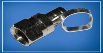
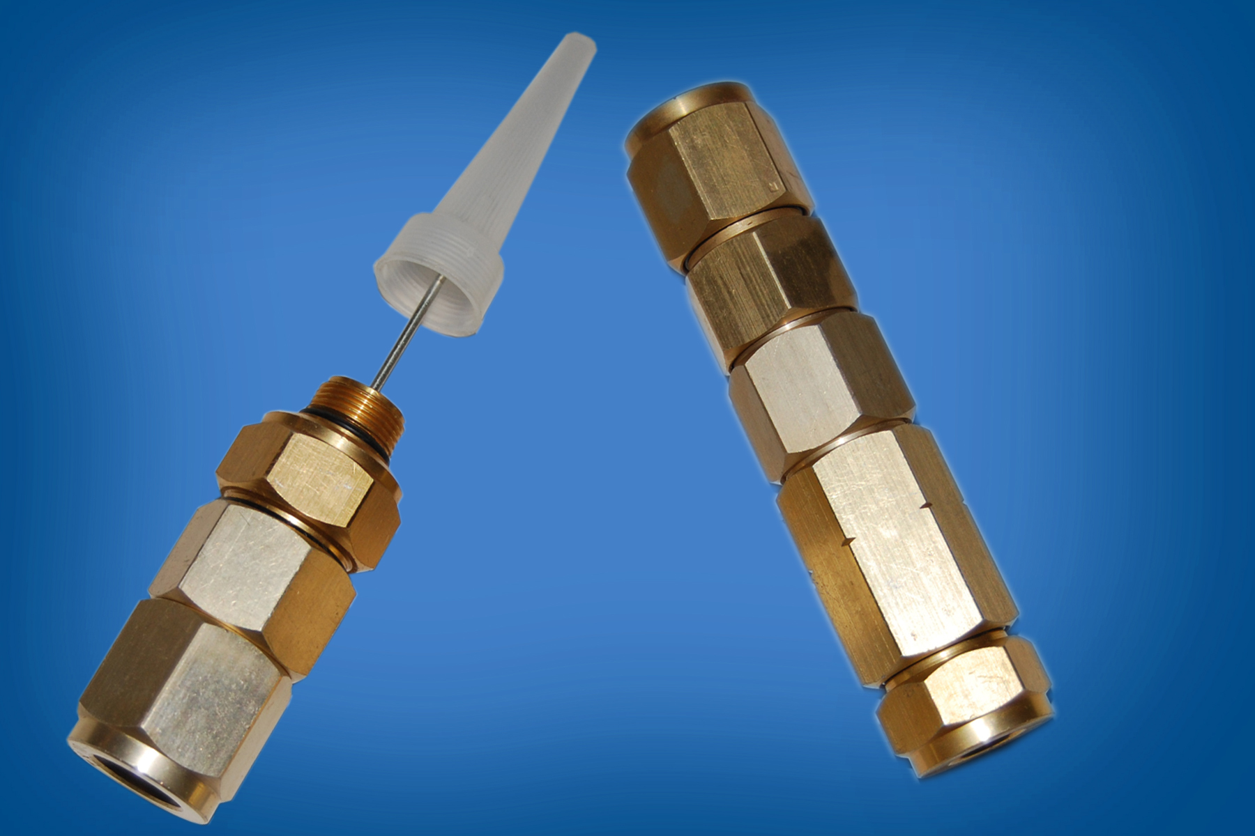
SMA (F) S/T jack to SMA (M) S/T plug quick lock adapter
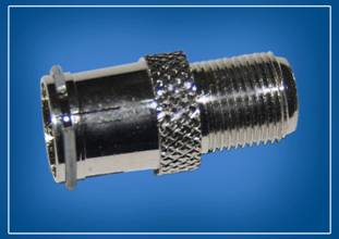
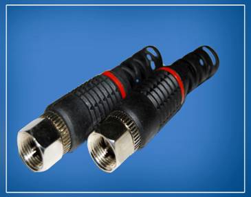
F Connector with 1/4 Crimp Ring
:
Connector for RG 6, RG 59
F Connector with 1/5 crimp Ring
:
Connector for RG 11
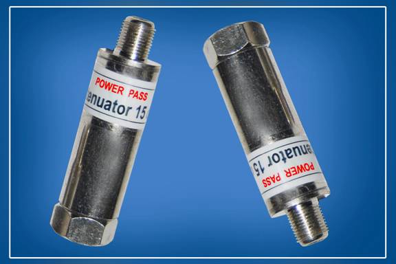
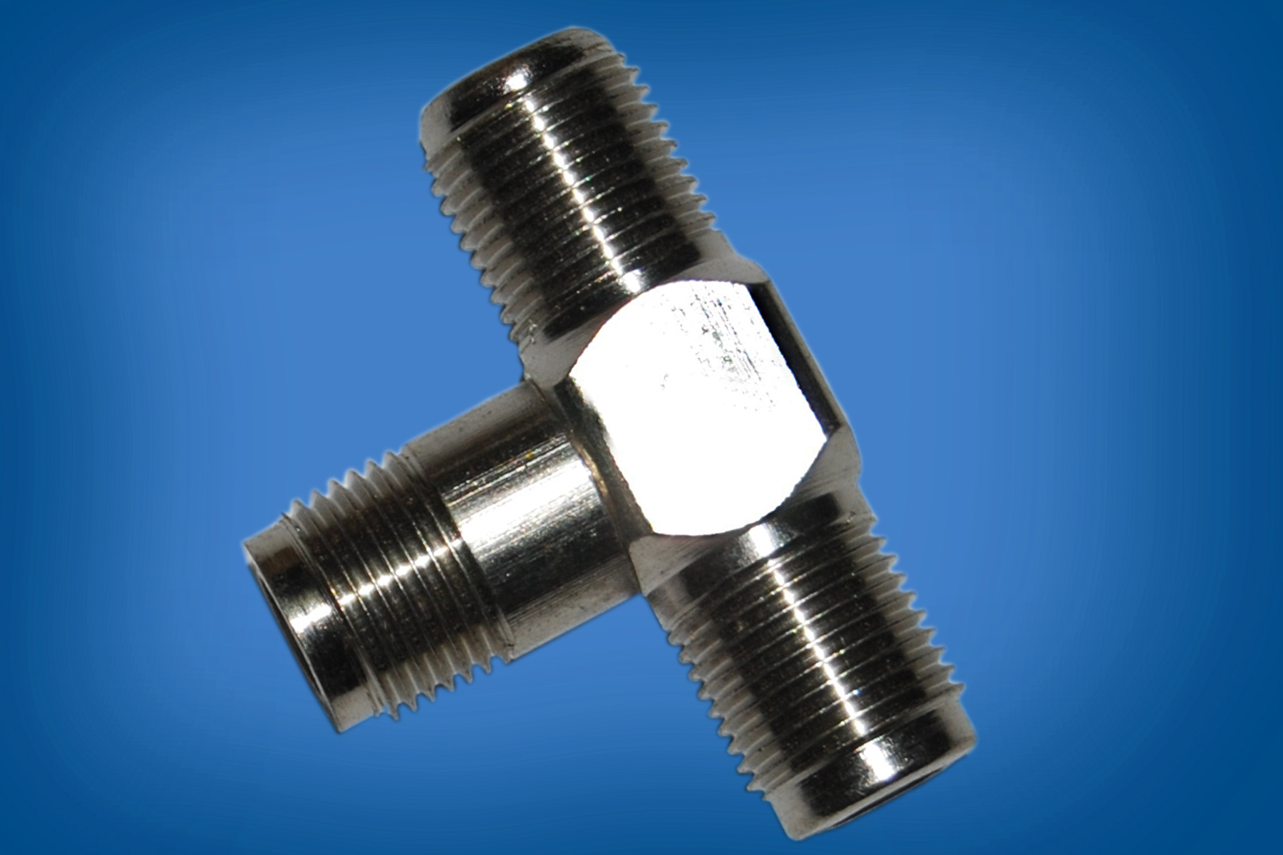
T-jointer
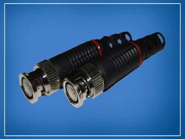
500 series connectors
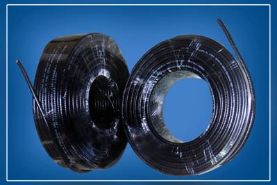
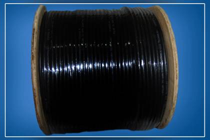
Cables:
Brands
Optitech, Zentech, Foam Tech, Zenex
RG 6 Series - Drop Cable
SPECIFICATIONS
PHYSICAL DIMENSIONS
Component
Standard (Inches)
Shield (mm)
Nominal Center Conductor Diameter
0.040
1.02
Nominal Diameter Over Dielectric
0.180
4.57
Nominal Diameter Over First Shield (Tape)
0.187
4.75
Nominal Diameter over Jacket
0.272
6.91
Nominal Jacket Wall Thickness
0.030
0.76
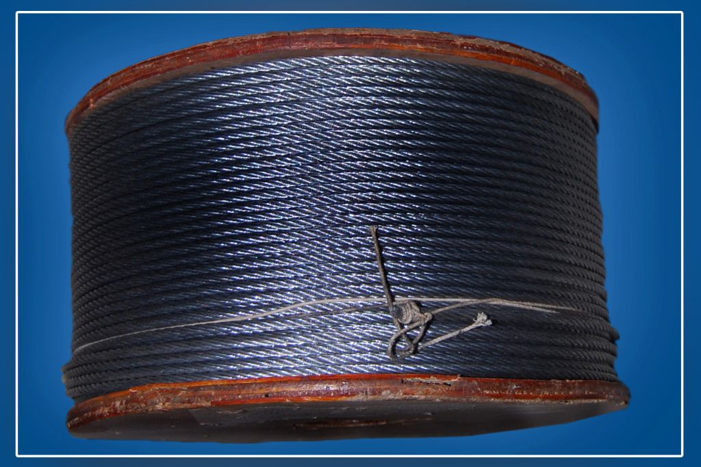
Nominal Diameter Of Steel Messenger (Single)
0.051
1.30
Nominal Diameter Of Steel Messenger (Dual)
0.072
1.83
Mechnical Characteristics
Minimum Breaking
0.051
180lbs
82 kg.
Strength of Messenger
0.072
3651bs
166 kg.
Electrical Characteristics
Nominal Impedance 75 ohms
Nominal Velocity of Propagation 85%
Shielding Effectiveness > 100 dB
Standard Construction
18 gauge [0.040 in. (1.02 mm)] Solid Copper Center Conductor gas expanded polyethylene dielectric, inner shield aluminum -polypropylene aluminum laminated tape with overlap bonded to dielectric, outer shield of 38 AWG aluminum wire braided shield 'with jacket of polyvinylchloride or polyethylene (flooded) Nominal 0.0. 0.272 in. (6.91 mm)
Attenuation [@ 68 F. (20 C)]
Frequency ( MHz)
Maximum (dB/100m)
5
1.80
55
4.98
211
9.05
250
10.27
350
11.99
400
12.92
450
13.70
500
14.33
550
15.27
600
15.89
750
17.60
865
19.00
1000
20.50
1200
22.70
1450
24.99
1750
27.68
RG 11 Series - Drop Cable
SPECIFICATIONS
PHYSICAL DIMENSIONS
Component
Standard (Inches)
Shield (mm)
Nominal Center Conductor Diameter
0.064
1.63
Nominal Diameter Over Dielectric
0.208
7.11
Nominal Diameter Over First Shield (Tape)
0.287
7.29
Nominal Diameter over Jacket
0.395
10.03
Nominal Jacket Wall Thickness
0.042
1.07
Nominal Diameter Of Steel Messenger (Single)
0.072
1.83
Nominal Diameter Of Steel Messenger (Dual)
0.109
2.7
Mechnical Characteristics
Minimum Breaking
0.072
365lbs
166 kg.
Strength of Messenger
1.109
18001bs
1818 kg.
Electrical Characteristics
Nominal Impedance 75 ohms
Nominal Velocity of Propagation 85%
Shielding Effectiveness > 100 dB
Standard Construction
14 gauge [0.640 in. (1.63 mm)] Solid Copper Center Conductor gas expanded polyethylene dielectric, inner shield aluminum -polypropylene aluminum laminated tape with overlap bonded to dielectric, outer shield of 38 AWG aluminum wire braided shield 'with jacket of polyvinylchloride or polyethylene (flooded) Nominal 0.0. 0.395 in. (10.03mm)
Attenuation [@ 68 F. (20 C)]
Frequency ( MHz)
Maximum (dB/100m)
5
1.1
55
2.99
211
5.91
250
6.38
350
7.54
400
8.10
450
8.56
500
9.03
550
9.47
600
9.90
750
11.37
865
12.39
1000
13.55
1200
15.05
1450
16.90
1750
19.95
Cables:
Brands
Digital Upgrade Co-Axial Cables
CONSTRUCTION RG59 F, RG6 F & RG 11 F
Solid bare electrolytic grade copper conductor Gas injected physical foam dielectric
Poly-laminated aluminum tape
Aluminum braiding with high tensile strength
UV resistant outer PVC jacket
Parameters
Drop
RG 59 F
Drop
RG 6 F
Drop
RG 11 F
CONSTRUCTION
Inner Conductor
Solid Bare Copper
Solid Bare Copper
Solid Bare Copper
Nominal Diameter Over Dielectric (mm)                                        Â
0.80
3.55
1.63
Dielectric
Foam PE
Foam PE
Foam PE
Nominal Diameter Over First Shield (mm)
3.55
4.57
7.11
Outer Conductor
First
Bonded AI Tape
Bonded AI Tape
Bonded AI Tape
Second
AI Braid
AI Braid
AI Braid
Nominal Coverage (%)
60
60
60
Flooding Compound
Jelly
Jelly
Jelly
Jacket
PVC (Black)
PVC (Black)
PVC (Black)
Nominal Diameter
6.20
7.0
10.0
Electrical
Inner Conductor Maximum Resistance (Ohm/100m) at 20°C Loop Resistance (Ohm/100m) at 20°C
3.55
4.64
2.13
2.78
0.84
1.66
Nominal Capacitance (pf/mtr.)
53
53
53
Nominal Impedance (Ohm)
75
75
75
Nominal Velocity Ratio (%)
85
85
85
Attenuation @ 20°C
Frequency MHz
dB/100m
Max.
dB/100m
Max.
dB/100m
Max.
5
2.82
1.95
1.25
55
6.73
5.20
3.15
83
8.04
6.20
3.87
187
11.81
9.15
5.74
211
12.47
9.50
6.23
250
13.45
10.5
6.72
300
14.60
11.50
7.38
350
15.75
12.45
7.94
400
16.73
13.30
8.53
450
17.72
14.35
9.02
500
18.70
14.95
9.51
550
19.52
15.70
9.97
600
20.34
16.45
10.43
750
22.87
18.35
11.97
865
24.67
19.95
13.05
100
26.64
21.45
14.27
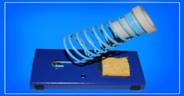
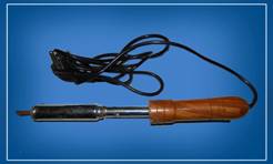
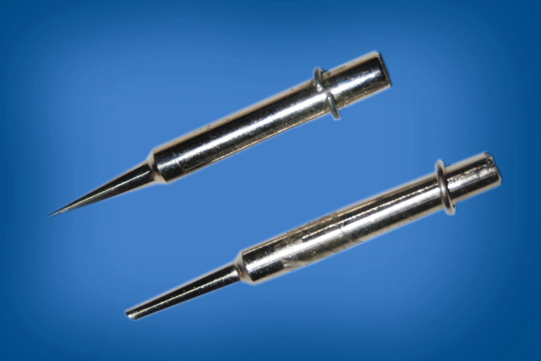
Soldering Iron/Solder Wire
Soldering Iron Stand
Soldering Iron
Soldron
:
25 , 35, 50 W
Dynamax
:
25/40 W
Janta
:
65/100/125/150/250
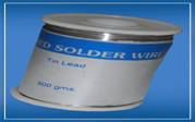
Solder Wire
18,20,22 Gauge
:
1/2 KG
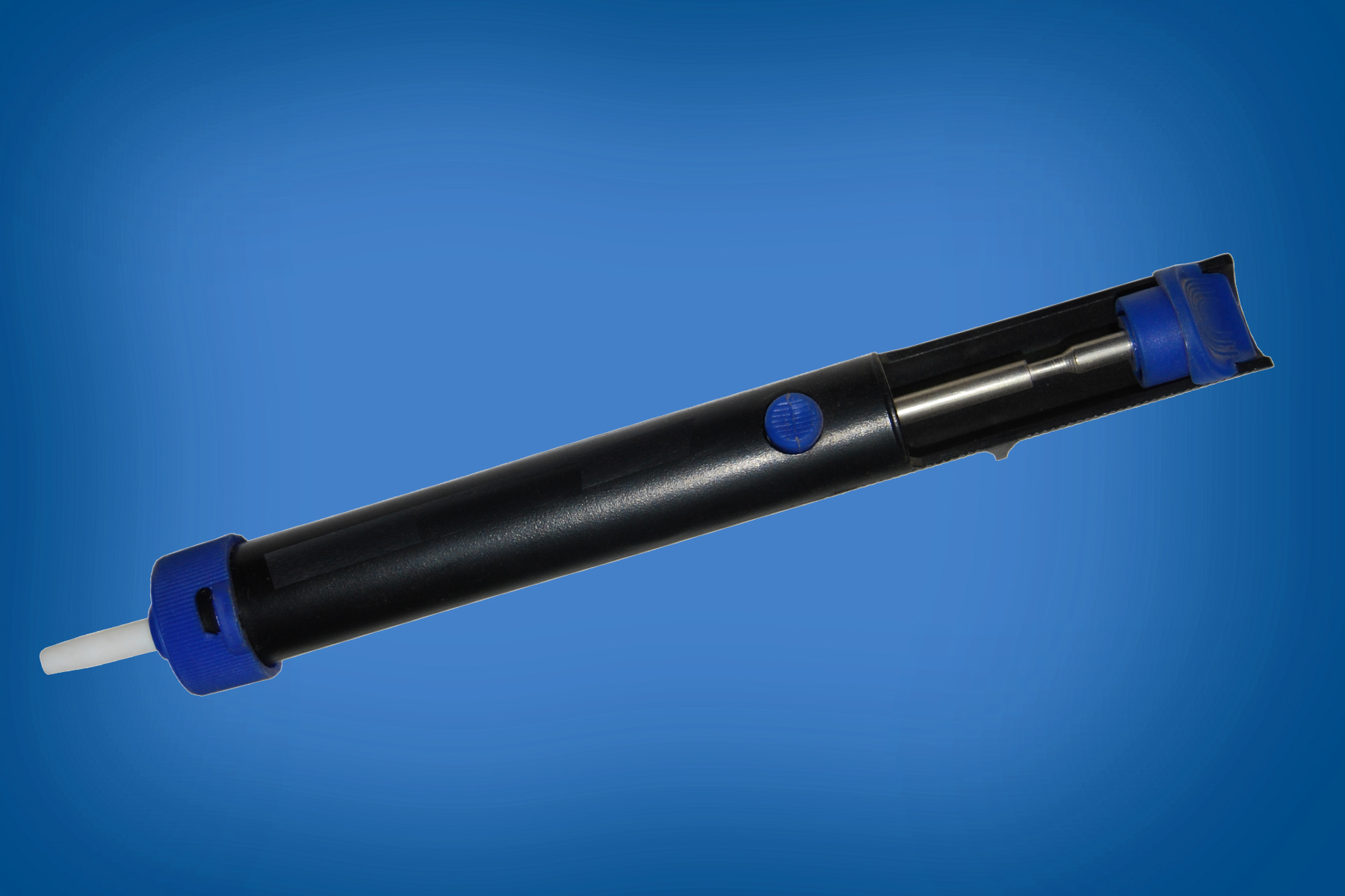
De-soldering pump
Soldering iron bits 25w, 50w, 100w
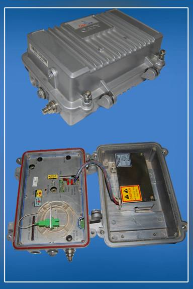
Optical Receiver / Node:
Brand
Optic Link
BroadCom
Specifications
Frequency Range:- 47 MHz 0 870 MHz
Optical Operating Wave length:- 1200 -- ~1600nm
Optical Amplifier with RF Input.
Operational Gain: 110 dBuV
Return Path optional Upgradable.
3V1PS suitable to work between 30--90 & 180--240 VAC.
External LED optical power meter to display the input optical power.
Fixed Equalizer and Attenuator Cards.
Equalizer card after Post Amplifier.
Number of Outputs: 2 with KS pin type to F connector
Test point: -20 dBuV at input and output stages.
Good Quality & Big Size Casing for outdoor use.
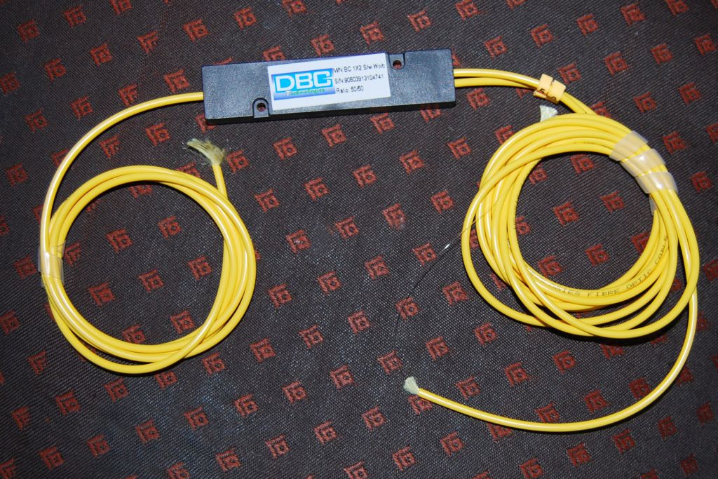
Optic Coupler
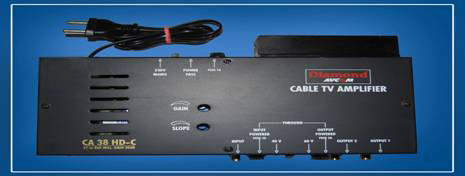
Amplifiers:
Brand
Diamond
HyBrid Amplifier
AGC Amplifier
Hybrid Amplifier
Specifications
Gain :-
30 or 40 dB for 550 MHz. 28 dB for 750 / 860 MHz.
Gain Flatness: -
± 0.75 dB for 30 dB. ± 1.5 dB for 40 dB.
Frequency Range: -
47 to 550 / 750 / 860 MHz.
Linear Power Supply :-
40 V / 60 V (Power Pass) or 230 V Mains Option
Gain Control :-
0 to -20 dB Variable
Slope Control :-
0 to -18 dB Variable
Monitor :-
12 dB
Second port power passing option.
Plug in cards Slope cards 6, 9,12,15 dB. 10 dB amplifier card to change gain from 30 dB to 40 dB. (for 550MHz)
Output card splitter/tap off.
MODELS:
CA 35 HD ( 30 dB / 550 MHz)
CA45 HD (40 dB / 550 MHz)
CA 37 HD ( 28 dB / 750 MHz)
CA38 HD (28 dB / 860 MHz)
AGC Amplifier
Specifications
Gain :-
30 ± 8 dB for 550Mhz 28 ± 8 dB for 860Mhz
Gain Flatness :-
± 1dB
Frequency :-
47 to 550 /750/860 MHZ
Manual Variable Slope Control :-
0 to -18dB
Manual Variable Gain Control :-
0 to -20 dB
Plug in Fixed Slope cards facility :-
Slope Cards of 6, 9,12,15 dB.
Output card splitter/tap off
Facility of powering 2nd output port (monitor) through switch inside amplifier
Automatic Gain control ± 8 dB i.e no change in output even if input changes by ± 8 dB
Linear Power Supply
40 V / 60 V (Power Pass) or 230 V Mains Option
Ref Channel for Monitoring O/P - Ch 12
MODELS:
AGC 305 (30 dB/550 MHz)
AGC 750 (28 dB/750 MHz)
AGC 860 (28 dB/860 MHz)
AGC Amplifiers are available in original Philips IC and Korean IC
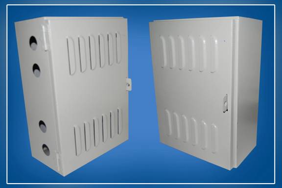
Amplifier Boxes
Specially Fabricated Amplifer boxes for Outdoor use. Lock facility available.
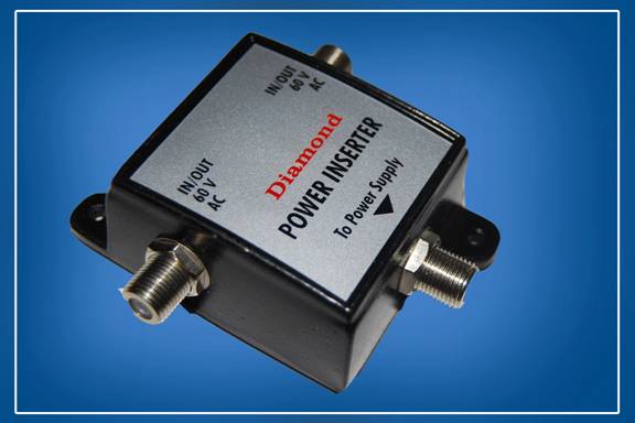
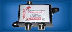
Power Inserter:
Brand
Diamond
Available in two models
One Way
Two Way
Power Capacity : 15 Amp . 60/90 V AC . 50/60 Hz
Impedance :- 75 Ohms
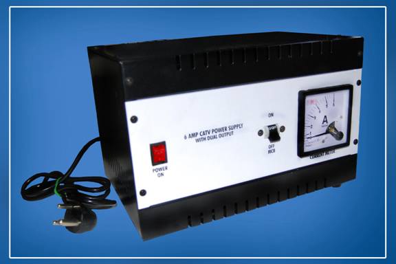
CATV Power Supply:
Brand
Diamond
Dual Output
Powering Power Pass Versions of Amplifier
Available in 6 and 10 Ampere rating
Output Voltage :- 60 V AC
MCB Protection against overload and short circuit
Current Meter and Power Indication
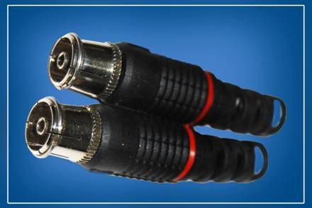
TV Pin/Box Type Pin/RF Plug Connector Box Type:
Brand
MX
Aspen
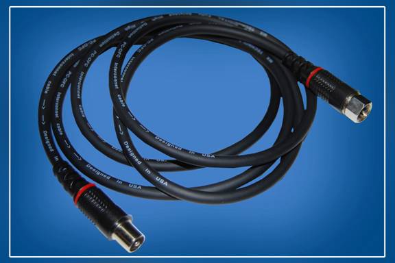
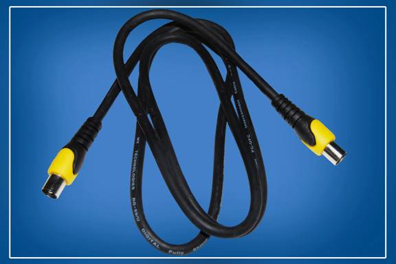
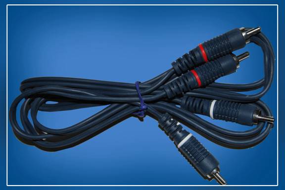
RF Cords:
F to Male
Male to Male
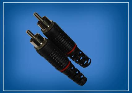
2 RCA to 2 RCA
RF Male/Female Pins
RF Male/Female Pins
RF Male/Female Pins
RF Male/Female Pins
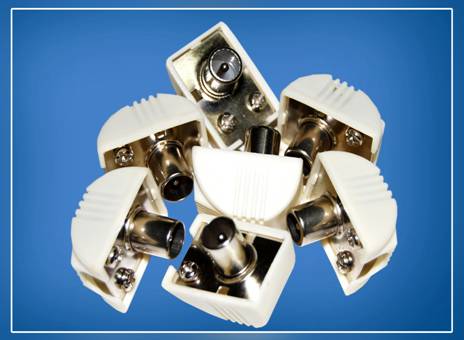
Splitters:
Brand
Diamond
2- Way , 3-Way , 4- Way Splitter
All Port Power Pass
860Mhz
Loss <= 6db
Single Port Power Pass
860Mhz
Loss <= 5db
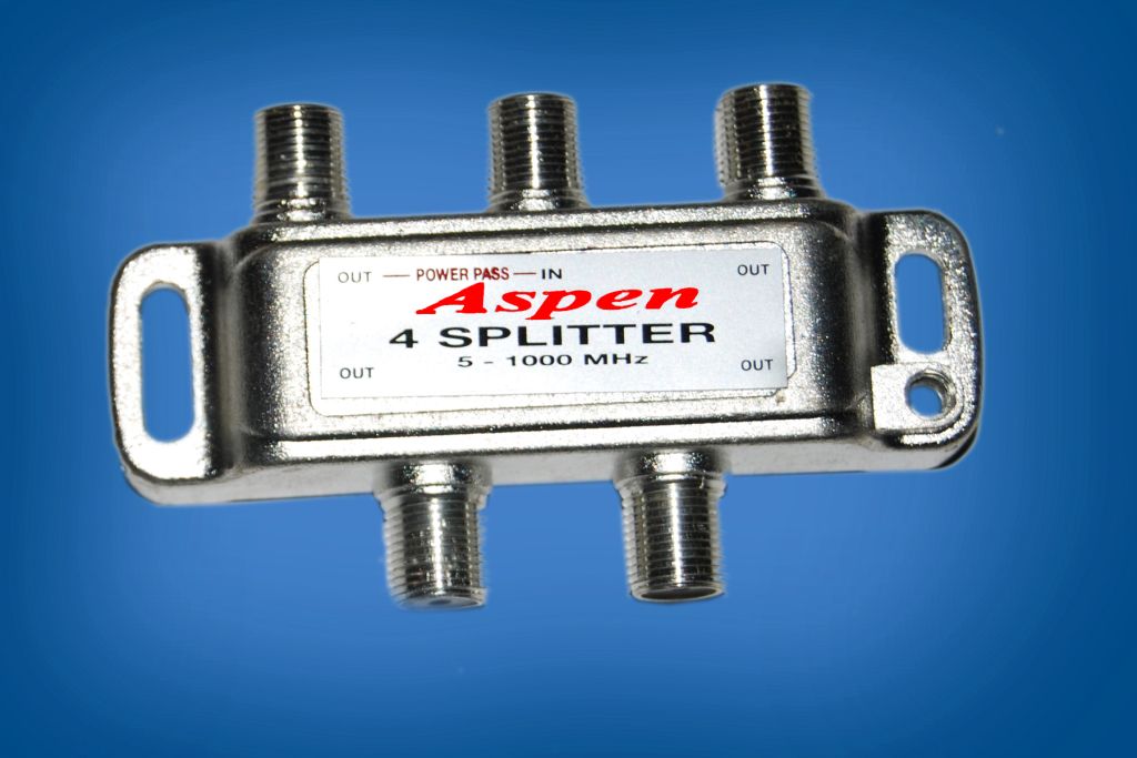
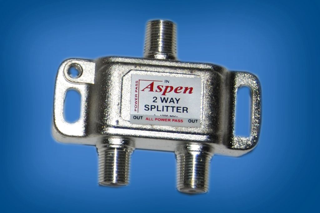
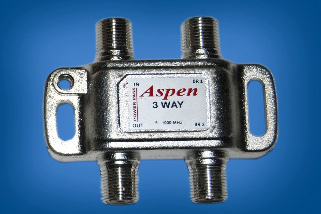
Aspen
2- Way , 3-Way , 4- Way Splitter
All Port Power Pass
1000Mhz
Loss <= 7db
Single Port Power Pass
1000Mhz
Loss <= 6db
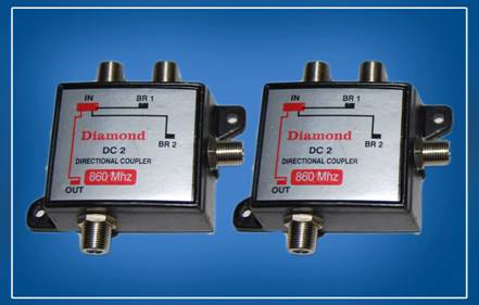
Tap Off:
Brand
Diamond
1- Way BR, 2- Way BR , 3-Way BR , 4- Way BR
860Mhz
In -out Loss <= 6db BR Loss <=10 db
Aspen
1- Way, BR 2- Way BR , 3-Way BR , 4- Way BR
1000Mhz
In -out Loss <= 6db BR Loss <=10 db
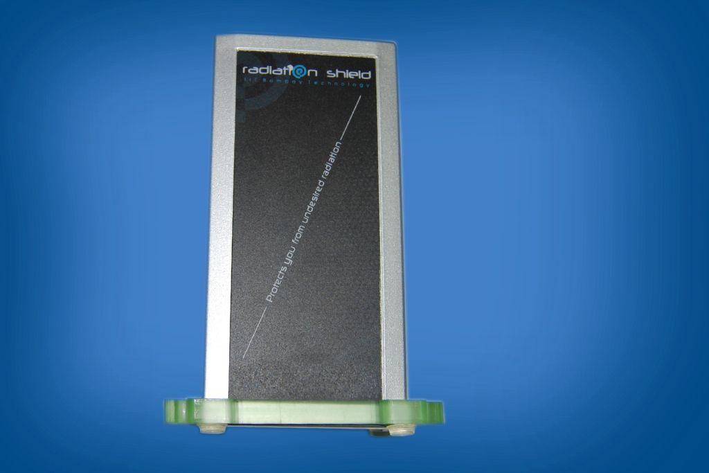
Radiation Shield:
Radiation Shield
Radiation emitted from Cell Phones, Cell phone towers, Wi-Fi, TV and FM towers, microwave ovens, etc are called Electromagnetic radiations and are known to cause significant Biological effects on the human body and health of animals.
Children are more prone to these effects as their skulls are thinner and still developing. Studies show that long-term exposure to radiation increases the risk of all forms of cancer, tumors, blood disorders, miscarriage, headaches, insomnia, anxiety, aging of the skin, skin burn, etc. Bioinitiative Report
Man-made electromagnetic fields have been steadily increasing with growing electricity, electronics and wireless communication demand. RADIATION is actively present in our environment more than ever before! We have reached A SUBTLY INFECTIOUS STAGE of our ambitious civilization where each of us is vulnerable and must seriously consider changes in our daily surroundings and habits; very specifically, apply remedial attention to our physical bodies now . . . not later.
WHAT IS THE RADIATION SHIELD?
The Radiation shield is an effective measure to prevent these harmful radiations from invading our lives. The size of the radiation shield is 180mm x 90mm x 30mm and can be placed on a table, mounted on the wall or fixed on a glass window. By placing a number of radiation shields in a room, radiation reduces proportionately from mobile phone towers, computers, microwave ovens etc.
Our radiation shield contains a LED, which glows when the mobile instrument or any high radiation emitting source is brought close to it, even though the device does not contain any battery. This demonstrates the high intensity of the electromagnetic energy emitting device.
HOW DOES THE RADIATION SHIELD WORK?
The Radiation Shield attracts the electromagnetic radiations present in an environment between the frequency range of 800MHz to 4 GHz and dumps it into a matched load built inside, thereby protecting people in the near vicinity. Besides protecting us from cell tower radiations, it also protects us from computers, laptops, microwave oven, WiFi, 3G,lower WiMax Bands, etc.
Radiation Shield is a passive device, requires no electrical power supply to operate, is rugged and 100% maintenance free. The product works for a life time and comes with a 5 year warranty period